 100% Australian owned


Description
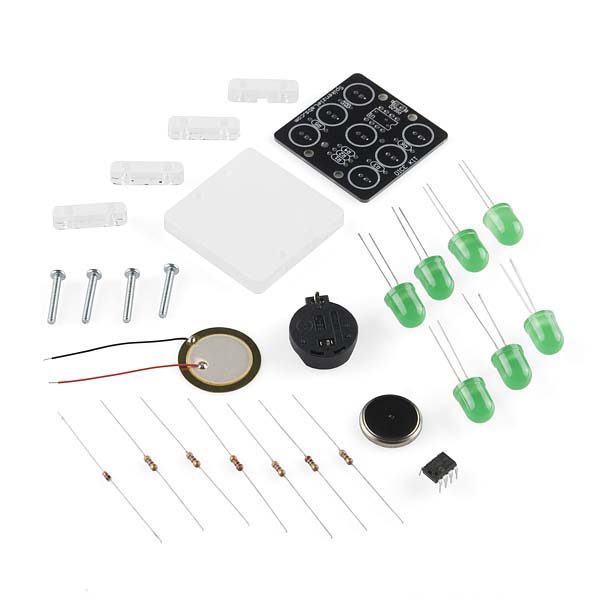
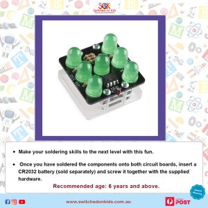
Dice with LEDs – Learn to Solder Kit: Take your soldering skills to the next level with this fun to build electronic dice. Once you have soldered the components onto both circuit boards, insert a CR2032 battery (sold separately) and screw it together with the supplied hardware. Shake the dice to generate a random number between one and six on the LEDs. You will need the usual Maker essentials, including a soldering iron, solder, and side cutters.
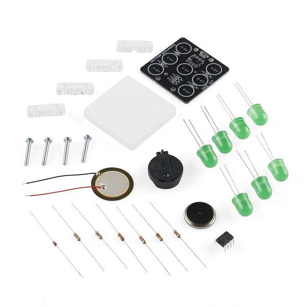
Here is our latest ‘easy build’ kit. Designed for beginners, the Dice Kit comes with everything you need to make your own ‘Electronic Die’. The name Dice kit sounds a great deal better than ‘Die Kit’, so we bent English grammar rules just a little in the name of making a marketable product.
What does it do?
Tap the DK on the table, and the LEDs light up and show a number from 1 through 6. After a short while, the DK goes into sleep mode, until the next time it is tapped. We have experimented with battery life, and even the oldest CR2032 battery that we had laying around the workbench, and used in other projects is still running in our production prototype.
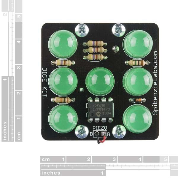
Why 7 LEDs for only 6 numbers? We have heard that a few times. Because we wanted to make the DK as realistic as possible, we needed the middle LED, as it is used in 1,3,5.
How does it work?
The principle is rather simple.
When you roll a regular Die on the table, it spins and lands with a top side, using the inertia from the person throwing or dropping it to randomize a result from 1 to 6. We know there are people out there with talents for ‘loading dice’… Well, they will have some difficulty loading these. Unless they have an aptitude for assembly language and reprogram the code on the PIC chip.
For the record, Spikenzie Labs does not condone gambling. However, we do think you’d be the coolest cat on the block if you showed up to a game of marbles with one of these.
The DK ‘reads’ the impact using the piezo sensor that you will be gluing to the bottom acrylic base.
This sensor reading enters the PCB as an analog voltage. A short burst of energy that passes through a voltage limiting, and direction setting Diode (D1). The Diode protects the somewhat sensitive PIC chip from an overvoltage.
Dice with LEDs: This reading, or we can call it a ‘Signal’ is read by the PIC on one of the 8 Legs. The reading is analog, the chip converts this analog information into a decimal value.
For Example, If the piezo sends 1.22348 volts into the PIC, it is interpreted as ‘1.22348’ volts. In order to obtain a random result between 1 and 6, we have developed a way of converting results to 1-6 by a reading from the least significant decimal place; we use that information to generate the associated number on the face of the DK.
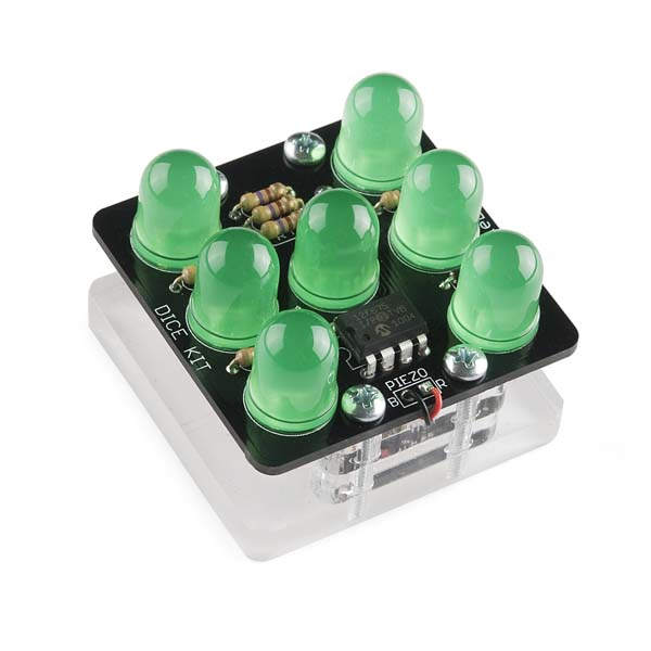
The 10mm chunky LEDs are connected through resistors to the PIC chip and light up the result. In fact, the LEDs are actually flashing on and off. The PIC found on the DK has a limited number of pins, so the seven LEDs are controlled by four pins. After a pause of about 15 seconds, the PIC enters sleep mode and turns off the LEDs.
In sleep mode, the PIC is in a very low power mode. The instant the DK is struck, the piezo sends a pulse that immediately wakes up the PIC, and starts running the program once again.
Recommended Age
Age: 6+


Reviews
There are no reviews yet.